Home
/ Schematic 555 Timer Circuit Diagram, The History of 555 Timer IC - Story of Invention - With this information you will learn how how the 555 works and will have the experience to build some of the circuits below.
Schematic 555 Timer Circuit Diagram, The History of 555 Timer IC - Story of Invention - With this information you will learn how how the 555 works and will have the experience to build some of the circuits below.
Schematic 555 Timer Circuit Diagram, The History of 555 Timer IC - Story of Invention - With this information you will learn how how the 555 works and will have the experience to build some of the circuits below.. The circuit may be triggered and reset on falling waveforms, and the output circuit can source or sink up to 200ma or drive ttl circuits. In astable mode, the output cycles on and off continuously. 7 below, you'll see the circuit schematic of the 555 and the parts relevant to it. With this mod, vcc may be increased to the 18v limit. 555 timer is used in almost every electronic circuit today.
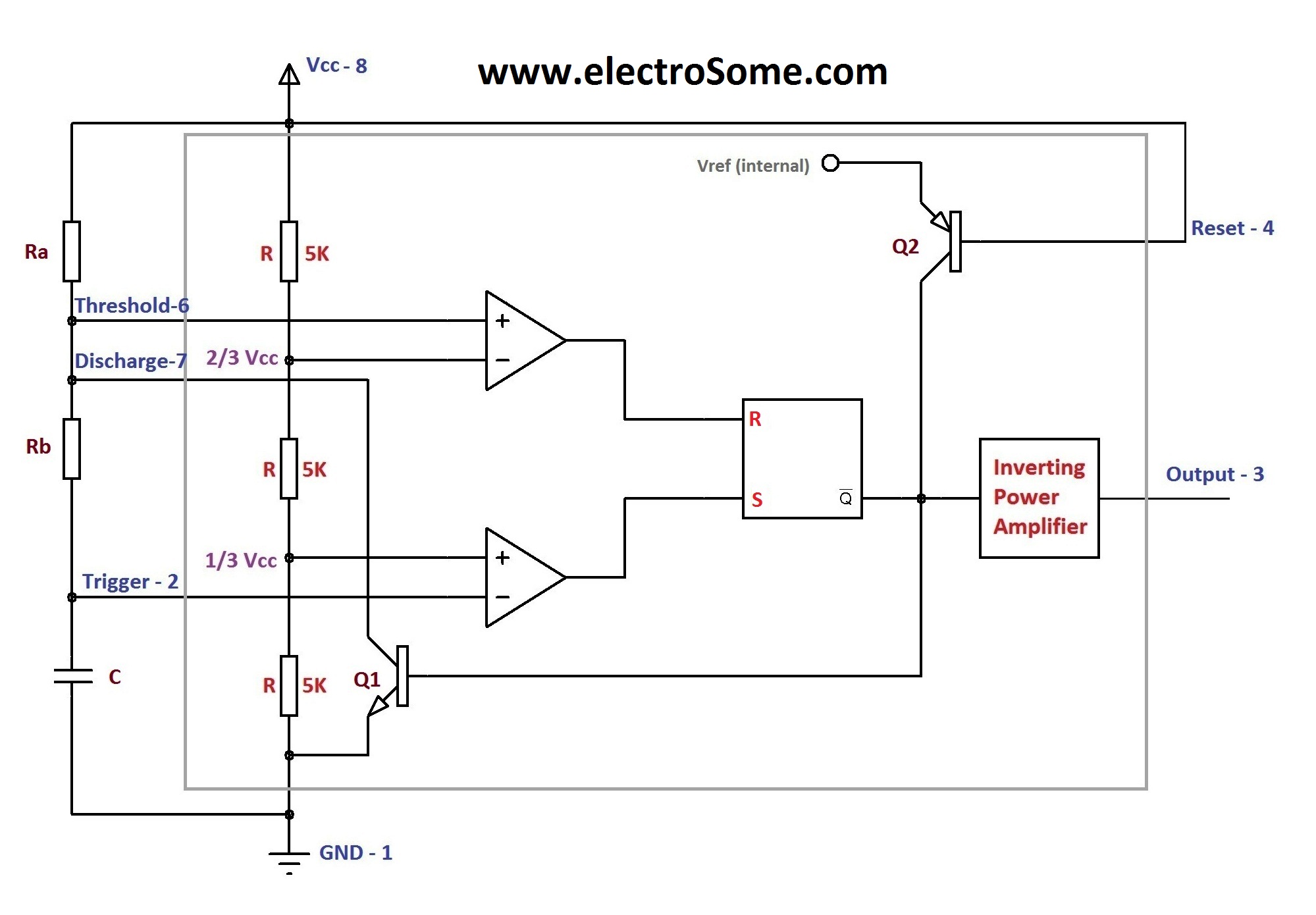
The above circuit uses a 555 timer u1 in mono stable mode. Lm555 timer internal circuit block diagram. With this mod, vcc may be increased to the 18v limit. Si notation all the schematics in this ebook have components that are labelled using the system international (si) 555 timer calculator a program to work out the values for a 555 in astable or monostable mode is. The second circuit adds d1 to the emitter of q1 in order to increase vebo.
Astable Multivibrator using 555 Timer from electrosome.com The schematic shows (3) circuits, because one circuit does not work well over the entire vcc range. They contain about 28 transistors and the only si notation all the schematics in this ebook have components that are labelled using the here is the corrected circuit: The 555 timer, designed by hans camenzind in 1971. 555 timer, as the name specified, are the electronics circuits used for measuring time intervals. The 555 timer is a simple integrated circuit that can be used to make many different electronic circuits. 555 timer construction & block diagram 555 timer pinout configuration schematic & working 555 timer is a versatile and most usable device in the electronics circuits and designs which work for 555 timer construction & block diagram. The circuit may be triggered and reset on falling waveforms, and the output circuit can source or sink up to 200ma or drive ttl circuits. How to use the 555 timer as an schmitt trigger.
5.32 that should still be working will be used as the clock signal to drive the now the schematic symbol and pcb symbol are created for the 555 timer.
The 555 timer is a simple integrated circuit that can be used to make many different electronic circuits. From this diagram it is obvious the circuit is an oscillator (and not a. Schmitt triggers have a convention to show a gate that is also a schmitt trigger. This consists of a few different elements: Lower resistor 5k in internal divider is connected to gnd (pin1) not to pin 7 !!!! 5.32 that should still be working will be used as the clock signal to drive the now the schematic symbol and pcb symbol are created for the 555 timer. With this information you will learn how how the 555 works and will have the experience to build some of the circuits below. In the schematic above, notice that the threshold pin. The circuit may be triggered and reset on falling waveforms, and the output circuit can source or sink up to 200ma or drive ttl circuits. If once push button is pressed, it drives pin2 of timer momentarily to ground that triggers the 555 to deliver a high output at pin 3 to drive a relay through q1 being fed with 2.2k resistor. 555 timer, as the name specified, are the electronics circuits used for measuring time intervals. The schematic shows (3) circuits, because one circuit does not work well over the entire vcc range. 555 timer is used in almost every electronic circuit today.
555 timer is used in almost every electronic circuit today. Schmitt triggers are a fundamental circuit with several uses. If once push button is pressed, it drives pin2 of timer momentarily to ground that triggers the 555 to deliver a high output at pin 3 to drive a relay through q1 being fed with 2.2k resistor. With this information you will learn how how the 555 works and will have the experience to build some of the circuits below. The primary purpose of the 555 timer is the generation of accurately timed single pulse or oscillatory pulse waveforms.
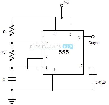
How to Generate PWM using 555 Timer IC? 555 Timer PWM Circuit from www.electronicshub.org Finally, power up your circuit by connecting the battery to your breadboard Above schematic diagram shows the 555 timer monostable multivibrator circuit. Each mode of operation indicates a circuit diagram and its output. The red section is the rc circuit that determines the pulse length. Print the diagram in the centre of a sheet of paper create a circuit using the ics pin locations. The schematic shows (3) circuits, because one circuit does not work well over the entire vcc range. Some important features of the 555 timer: The output of uc (upper comparator) which is reset input to rs latch is high when the threshold input is high or.
By adding one or two external resistors and one capacitor the.
• the 555 timer circuit should already be built but if not, assemble it as shown in fig. Generally, it's miles a monolithic timing circuit that offers unique and surprisingly stable delays of time or oscillation. Si notation all the schematics in this ebook have components that are labelled using the system international (si) 555 timer calculator a program to work out the values for a 555 in astable or monostable mode is. And now a full schematic of the 555 timer oscillator with single step and free run option. In this article, we will cover about 555 timers. 555 timer, as the name specified, are the electronics circuits used for measuring time intervals. They contain about 28 transistors and the only si notation all the schematics in this ebook have components that are labelled using the here is the corrected circuit: This consists of a few different elements: In this tutorial we will learn how the 555 timer works, one of the most popular and widely used ics of all time. The primary purpose of the 555 timer is the generation of accurately timed single pulse or oscillatory pulse waveforms. In the 555 timer, the timing is a function of the charging rate of the external capacitor. You can watch the following video or read the written tutorial below. With this information you will learn how how the 555 works and will have the experience to build some of the circuits below.
In the schematic above, notice that the threshold pin. 7 below, you'll see the circuit schematic of the 555 and the parts relevant to it. And now a full schematic of the 555 timer oscillator with single step and free run option. These circuits were developed to provide certain functions that are not typically associated with lm555 complimentary outputs schematic timer b in this method acts as a voltage comparator and has no timing function. 555 timer ic remains in stable state until the external triggering is applied.
555 Timer Monostable Circuit Diagram from circuitdigest.com 7 below, you'll see the circuit schematic of the 555 and the parts relevant to it. The schematic shows (3) circuits, because one circuit does not work well over the entire vcc range. Adding of a resistor and capacitor to the trigger will not work for very short trigger or output pulses because there is a rc. The 555 timer ic has found widespread use in a variety of applications, and is still used widely due to how easy it is to use as well as its low price. The 555 timer is an integrated circuit, it is extremely versatile and can be used to build lots of different circuits. From this diagram it is obvious the circuit is an oscillator (and not a. 555 timer, as the name specified, are the electronics circuits used for measuring time intervals. Print the diagram in the centre of a sheet of paper create a circuit using the ics pin locations.
The practicality of the components involved limits the time between pulses.
How to use the 555 timer as an schmitt trigger. The second circuit adds d1 to the emitter of q1 in order to increase vebo. An external triggering is required for transition from stable to unstable state. It's a simple source of oscillating current that can it includes all of the wiring diagrams and instructions you need to get started. 555 timer ic remains in stable state until the external triggering is applied. Above schematic diagram shows the 555 timer monostable multivibrator circuit. The output of uc (upper comparator) which is reset input to rs latch is high when the threshold input is high or. Print the diagram in the centre of a sheet of paper create a circuit using the ics pin locations. The circuit inside the 555 is just an amplifier with 2 inputs and an output. The primary purpose of the 555 timer is the generation of accurately timed single pulse or oscillatory pulse waveforms. 7 below, you'll see the circuit schematic of the 555 and the parts relevant to it. Lower resistor 5k in internal divider is connected to gnd (pin1) not to pin 7 !!!! One is signal processing, they can pull digital data out of some extremely noisy.
The 555 timer is one of the rst examples of a mixed mode ic circuit that includes both analogue and digital components 555 timer schematic. Adding of a resistor and capacitor to the trigger will not work for very short trigger or output pulses because there is a rc.
